
Resin-Cast Wi-Fi Desk Clock with Environmental Sensing and LED Filaments
A clear resin desk clock combines temperature and humidity readings, five animated light filaments, and a proximity response with a phone-accessible page.
Overview
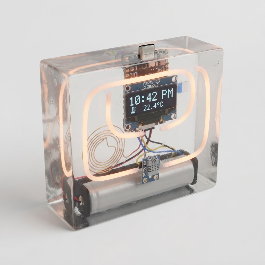
This desk ornament places a small display, environmental sensor, and five flexible light filaments inside a clear cast body. The display cycles through clock and sensor pages, while separate lighting channels provide a steady glow, status flashes, and animations. A brass electrode near the front is intended to make the light respond to an approaching hand.
A wireless controller provides network time and a small browser interface for viewing readings or sending display text. The sensor needs an opening to room air, and the programming connector needs a clear access path. Those two openings must be planned before casting rather than drilled toward embedded electronics afterward.
The visible brass supports are both structure and decoration. Printed mounts locate the filaments and electrode during the pour. Casting makes the arrangement permanent, so the complete circuit needs to work on the bench first; a serviceable battery compartment or external power connection should be resolved before preparing the mold.
Parts
This parts table is seeded from the Blueprint project.
| Part function | Canonical name | Qty | Type | Size | Est. cost |
|---|---|---|---|---|---|
| Rectangular Casting Mold | Silicone Rectangular Epoxy Resin Mold | 1 | Misc | 105x60x40mm | $9.00 |
| Clear Resin Cast Body | LET’S RESIN Clear Epoxy Resin Casting Kit | 1 | Enclosure | 100x55x35mm | $8.00 |
| Portable Power Battery | 18650 Lithium-Ion Battery 3.7V | 1 | Power | 65x18.3x18.3mm | $8.00 |
| Filament (Seconds Blink, Frame Glow, Status Flash, Proximity Ramp, Text Wave) | 3V Flexible LED Filament | 5 | Actuator | 130x2x2mm | $7.50 |
| Temperature Humidity Sensor | SHT3X I2C Temperature and Humidity Sensor Module | 1 | Sensor | 16x13x3mm | $6.50 |
| Clock and Sensor Display | 0.91-inch 128x32 I2C OLED Display | 1 | Display | 38x12x4mm | $5.50 |
| Main Controller | ESP32-C3 Super Mini | 1 | Controller | 22.5x18x4mm | $4.50 |
| 18650 Battery Retainer | Keystone 1042 Single 18650 Battery Holder | 1 | Misc | 77x21x18mm | $2.50 |
| Internal Insulation Sheet | 0.5mm PET Electrical Insulation Sheet | 1 | Misc | 100x55x0.5mm | $1.00 |
| Clear Non-Slip Feet | 3M Bumpon Clear Rubber Feet | 4 | Misc | 10x10x3mm | $0.72 |
| Hand Proximity Antenna | Bare Brass Wire Electrode | 1 | Sensor | 100x1x1mm | $0.50 |
| Sensor Vent Casting Mask | Reusable Silicone Putty | 1 | Misc | 15x12x8mm | $0.50 |
| USB Port Casting Mask | Reusable Silicone Putty | 1 | Misc | 12x8x6mm | $0.50 |
| Display Brass Support | 1.5mm Solid Brass Craft Wire | 1 | Structural | 90x1.5x1.5mm | $0.35 |
| Controller Brass Support | 1.5mm Solid Brass Craft Wire | 1 | Structural | 80x1.5x1.5mm | $0.30 |
| Sensor Brass Support | 1.5mm Solid Brass Craft Wire | 1 | Structural | 60x1.5x1.5mm | $0.25 |
Estimated total for the modeled parts: $55.62.
How It Works
The controller shares an I2C bus between the 128×32 display and the temperature-humidity module, using GPIO5 for data and GPIO6 for clock in the modeled assignment. Both peripherals use the 3.3 V domain. Firmware updates the display from sensor samples and network time, while its browser page accepts short text messages and exposes the latest readings.
Five output channels on GPIO0 through GPIO4 represent seconds, steady illumination, status, proximity response, and text animation. Their PWM signals control brightness, but the modeled direct connections omit current-limiting and driver details. Complete those circuits from the filament and controller limits; reducing PWM duty cycle alone does not establish an acceptable peak current.
The proximity electrode is assigned to GPIO7. Its response depends on the actual sensing method, circuit, and firmware; a bare wire on a general-purpose input does not by itself establish a working capacitive sensor. Verify detection on the selected controller before casting, keep the electrode away from switching conductors, and recalibrate after its surroundings change from air to resin.
The power model connects a nominal 3.7 V cell to a controller input labeled 5 V, but does not provide a complete charging, protection, or source-isolation circuit. Resolve the accepted input range and USB interaction before using that arrangement. The embedded electronics and cell-access plan must be treated as separate decisions rather than assuming the entire assembly can be permanently encapsulated.
Build Steps
-
Resolve the electrical omissions. Complete the supply, battery protection and charging arrangement, filament current limiting or drivers, and proximity sensing circuit. Test the chosen input voltage and programming-power arrangement on the bench before committing to a layout.
-
Build and verify the display and sensor bus. Connect the I2C modules with the intended supply and pull-ups, confirm their addresses, and load the final pin assignments. Check clock synchronization, sensor pages, and the phone-accessible interface.
-
Test lighting and proximity together. Exercise each output separately, measure its current, and confirm that the controller starts reliably with all loads connected. Verify the electrode response with lighting and wireless activity running so interference is found before casting.
-
Prepare supports and the mold. Print and deburr the locating mounts, form the brass supports, and dry-fit the assembly. Leave clearance around the electronics and provide a serviceable power arrangement. Position masks that reach the mold wall at both the programming connector and the sensor opening.
-
Run the complete assembly before the pour. Insulate exposed joints and secure the parts so they cannot move. Test network reconnection, timekeeping, all lighting channels, display text, and sensor readings, then disconnect power and remove the battery from the casting operation.
-
Cast according to the selected material’s instructions. Check compatibility with the installed materials and follow the specified mix ratio, pour depth, handling precautions, and cure schedule. Do not assume a fixed 24-hour cure or heat the assembly to clear bubbles without a verified process.
-
Finish and repeat the functional checks. Remove the masks and clear the openings after curing, inspect for trapped or damaged parts, and reconnect the serviceable power source. Recalibrate proximity sensing in the finished body and check sensor response, lighting, network access, and programming access again.
See the complete build steps in Blueprint.
Notes
Permanence is the central tradeoff. A cast body makes repairs difficult, changes the electrode’s surroundings, and can bias the environmental sensor if its opening is obstructed or it is warmed by nearby circuitry. Prove the circuit and opening geometry before pouring, and keep the battery accessible rather than treating it as a decorative embedded component.
The Blueprint table describes the modeled parts, not a verified complete electrical design. The battery-input connection, absent charging and protection circuitry, direct filament drive, and proximity implementation need resolution; additional parts may change the cost and layout. Resin handling and cure limits depend on the selected formulation, so preserve its instructions as part of the build record instead of reusing a generic cure time.