
Experimental Variable-Pitch Quadcopter with Belt-Driven Rotors
An experimental quadcopter uses four belt-driven rotors and independent pitch servos to change thrust without relying only on motor-speed changes.
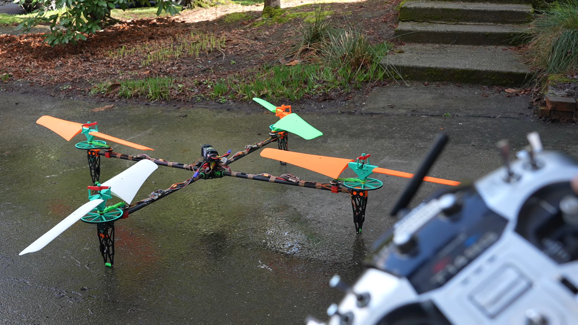
Overview
This aircraft explores a different way to control a multirotor: keep the rotors near a steady speed and change blade pitch to vary thrust. Each corner carries a brushless motor, belt drive, variable-pitch hub, and dedicated servo. The pitch mechanism changes how much air the blades move without requiring the motor to accelerate a large rotor for every correction.
The motivation is lower disk loading from a larger swept area. Larger rotors can support a given weight while accelerating the air less, but their inertia makes rapid speed changes harder. Pitch control addresses that response problem at the cost of a much more complicated rotor assembly.
This is an experimental platform. The model organizes the frame, electronics, printed mounts, hubs, and blade sets, but it does not establish validated structural loads, operating speeds, or flight settings. Those limits must be determined before a replica can be treated as flight-ready.
Parts
This parts table is seeded from the Blueprint project.
| Part function | Canonical name | Qty | Type |
|---|---|---|---|
| Brushless Motor (Front-Left, Front-Right, Rear-Left, Rear-Right) | Design-Dependent Brushless Drone Motor | 4 | Actuator |
| Drive Belt (FL, FR, RL, RR) | Design-Dependent Belt-Drive Components | 4 | Mechanism |
| ESC (Front-Left, Front-Right, Rear-Left, Rear-Right) | Design-Dependent Brushless-Motor ESC | 4 | Module |
| Flight Controller | Design-Dependent Quadcopter Flight Controller | 1 | Controller |
| Frame and Rotor Fasteners | Design-Dependent Frame and Rotor Fasteners | 48 | Misc |
| Frame Arm (FL, FR, RL, RR) | Custom Large Quadcopter Frame Arm | 4 | Structural |
| Main Flight Battery | Design-Dependent Flight Battery | 1 | Power |
| Main Frame Base Plate | Custom Large Quadcopter Center Frame | 1 | Structural |
| Pitch Servo (Front-Left, Front-Right, Rear-Left, Rear-Right) | Design-Dependent Pitch-Control Servo | 4 | Actuator |
| Power Distribution Board | Design-Dependent Power Distribution | 1 | Power |
| RC Receiver | Design-Dependent RC Receiver | 1 | Module |
| Regulator / Servo BEC | Design-Dependent Regulator / Servo BEC | 1 | Power |
How It Works
The flight controller sends four independent thrust commands to the pitch servos. Each servo moves its hub linkage, changing blade angle and therefore rotor thrust. A separate command path controls motor arming and speed through four electronic speed controllers. Correct servo direction and matched pitch travel are essential because a reversed response undermines the control loop.
Each motor drives its rotor through a belt. Belt alignment, bearing play, shaft runout, and linkage backlash affect both vibration and control response. The mechanical system therefore needs to be checked as a complete assembly rather than judging the motor and servo independently.
The battery feeds a distribution board and the motor controllers. A regulated supply powers the servos, while the flight controller and receiver need their specified supplies and common signal references. The model leaves several electrical ratings unspecified; select the regulator, wiring, connectors, and battery from the actual load requirements rather than filling those blanks with assumptions.
Changing pitch through neutral can produce reverse thrust, but that does not establish controllable autorotation. The design needs a defined response to lost radio input, stopped motors, and failed pitch commands independently of any reverse-pitch experiment.
Build Steps
-
Define the operating envelope and control paths. Resolve rotor geometry, materials, retention hardware, bearing loads, motor power, servo loads, and supply requirements. Configure independent pitch outputs and a separate motor arming and speed path before installing blades.
-
Prepare and inspect the structure. Assemble the frame and mounts, then inspect each hub, grip, blade, and linkage for cracks, voids, or inconsistent construction. Balance blades and match pairs; printed appearance alone is not evidence of adequate strength.
-
Wire and test without blades. Check the distribution and regulated supplies, connect the receiver, servos, and motor controllers, and verify motor direction. Test arming, shutdown, and radio-loss behavior with the rotors unable to generate thrust.
-
Calibrate the pitch mechanisms. Set neutral positions, match travel and direction across all four hubs, and establish mechanical stops. Move each linkage through its range while checking clearance, backlash, and binding.
-
Check the belt-driven assemblies. Verify alignment, tension, shaft runout, bearing play, and fastener retention. Confirm that servo movement does not pull a linkage into a belt or force the hub against a travel limit.
-
Conduct restrained rotor tests. Use suitable guarding and containment, test one rotor at a time, and stay outside the rotor plane. Increase operating conditions only within established limits while checking vibration, belt tracking, servo load, and structural condition.
-
Validate the integrated airframe before flight. Check coordinated pitch response and all shutdown paths under restraint. Proceed to controlled low-altitude testing only after the structural and control checks pass; keep reverse-pitch recovery experiments disabled until independently validated.
See the complete build steps in Blueprint.
Notes
Larger swept area can improve hover efficiency, but belts, linkages, rough blade surfaces, and extra mass reduce the benefit. Printed rotor vibration and the number of mechanical failure points are major practical concerns. No maximum speed, endurance, or safe blade specification is established by the modeled parts list.
Reverse pitch is an experimental capability, not a demonstrated recovery system. A loss of motor power still needs a tested response; do not assume autorotation will preserve control. The parts costs describe the modeled inventory and exclude whatever redesign, instrumentation, or test equipment is needed to establish a usable aircraft.