
Wi-Fi Voice Assistant with a Round Display and Phone-Based Controls
A compact voice assistant combines a microphone, speaker, animated round display, and a phone-accessible editor for conversational settings.
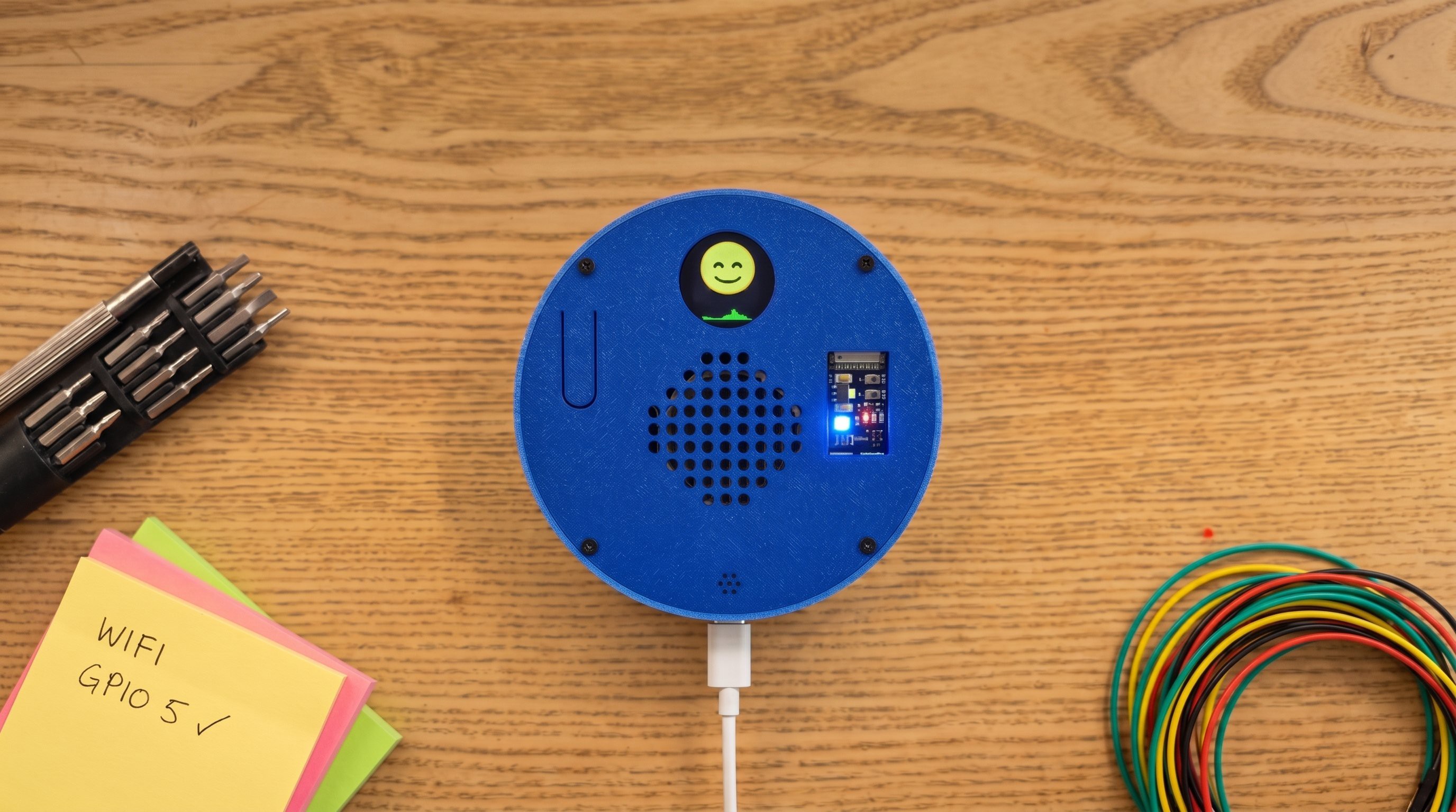
Overview
This tabletop device turns a push-button conversation into speech and an animated face. Hold the button to talk, release it to request a reply, and listen through the built-in speaker. A round 240×240 display provides visual feedback, while a status light distinguishes listening and playback.
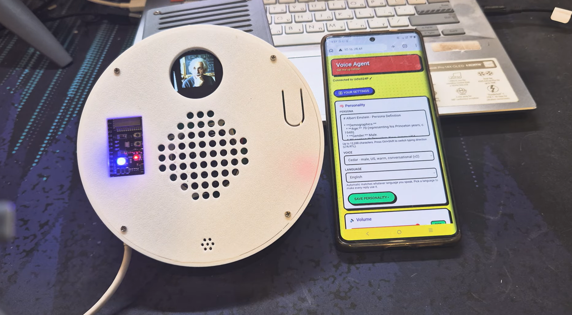
Its settings live in a browser interface served by the controller. A phone can edit the conversational instructions, voice selection, language, and display artwork without rebuilding the firmware. That makes the device useful for trying different characters or interaction styles on the same hardware. Settings persist across restarts, while speech processing depends on a network service.
The electronics fit inside a two-part circular enclosure with openings for the display, microphone, speaker, button, and programming connector. An optional audio converter supports an external audio path, but that option needs its own completed wiring and connector arrangement.
Parts
This parts table is seeded from the Blueprint project.
| Part function | Canonical name | Qty | Type | Size | Est. cost |
|---|---|---|---|---|---|
| Main Controller | ESP32-S3 N16R8 Development Board | 1 | Controller | 55x28x8mm | $8.50 |
| Round Face Display (Optional | GC9A01 240x240 Round SPI TFT Display | 1 | Display | 38x38x3mm | $6.00 |
| Headphone DAC (Optional | PCM5102A I2S Stereo DAC Module | 1 | Module | 28x20x4mm | $4.50 |
| Speaker Amplifier | MAX98357A I2S Class-D Amplifier Module | 1 | Actuator | 25x16x4mm | $4.00 |
| Voice Microphone | INMP441 MEMS I2S Microphone Module | 1 | Sensor | 25x15x6mm | $3.50 |
| Power and Data Cable | USB-C Data/Power Cable | 1 | Power | 1000x4x4mm | $3.00 |
| Voice Speaker | 1-3 W 4/8 Ohm Miniature Speaker, up to 57 mm | 1 | Actuator | 57x57x20mm | $2.50 |
| M3 Self-Tapping Mounting Screws | M3 Self-Tapping Screw Assortment | 12 | Misc | M3x10mm | $0.96 |
| M2 Self-Tapping Mounting Screws | M2 Self-Tapping Screw Assortment | 12 | Misc | M2x8mm | $0.84 |
| M3 Mounting Washers | M3 Stainless Steel Flat Washers | 12 | Misc | M3x0.5mm | $0.36 |
| Status Pixel | WS2812B 5 mm Addressable RGB LED | 1 | Display | 5x5x2mm | $0.20 |
| Push-To-Talk Button | 12x12 mm Tactile Momentary Push Button | 1 | Sensor | 12x12x7mm | $0.15 |
Estimated total for the modeled parts: $34.51.
How It Works
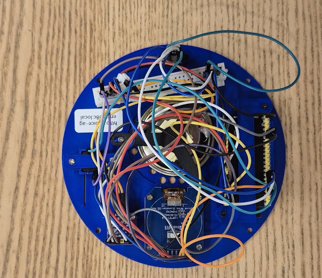
A wireless controller with external memory divides network traffic and real-time audio work between processing tasks. The microphone supplies digital audio over I2S; a separate I2S output sends playback samples to the speaker amplifier. Audio buffers absorb variation in network delivery so short delays do not immediately interrupt speech. Capture and playback use separate clock and data groups, even though a simplified connection graph can make them look shared.
The round display uses SPI. Rather than decoding animations on the controller, the browser converts artwork into raw frames before uploading it. Firmware reads the stored frames while audio plays, keeping image decoding out of the audio path. Firmware and display assets occupy separate storage areas and need separate uploads during bring-up.
Power is split between a 5 V amplifier supply and 3.3 V logic and peripheral supplies. The push button is a ground-referenced input with a pull-up, not a connection between two output pins. Final signal assignments, amplifier enable straps, and optional converter controls must agree with the firmware and the fitted module revisions; generic GPIO endpoints in the model are not a complete pinout.
Build Steps
-
Choose the audio configuration and finalize the pin map. Decide whether to fit only the speaker amplifier or include the optional audio converter. Assign separate capture and playback I2S groups, display SPI signals, the button input, and status output before making a permanent harness.
-
Prepare and dry-fit the enclosure. Print the shell and internal mounts, remove sharp edges, and check the actual board outlines against their trays. Align the microphone opening, speaker grille, display window, and programming connector before fastening the electronics.
-
Wire and check the power branches. With power disconnected, separate the amplifier supply from the logic rail and provide the required common reference. Confirm the voltage accepted by each fitted module, then check continuity and shorts before powering the controller alone.
-
Bring up input and playback independently. Connect the microphone and verify capture, then test the amplifier and speaker at low volume. Wire the button to its input and ground, enable the pull-up, and confirm one press produces one input event. Complete the converter’s mute, format, clock, and output wiring if that option is fitted.
-
Load firmware and artwork. Configure the installed flash and external memory, upload the program, and upload the display filesystem separately. Check that the default animation loads before trying custom artwork or a live conversation.
-
Configure and test the conversation loop. Enter network and service settings, open the browser editor, and save a short test persona. Verify capture, reply playback, volume changes, and display updates, then restart the unit to confirm settings persist. Exercise network loss and recovery as well as normal operation.
-
Close the enclosure and repeat the checks. Route cables clear of the speaker and case seam, provide strain relief, and check that microphone placement does not encourage feedback. Confirm the button, configuration page, and all audio modes still work after assembly.
See the complete build steps in Blueprint.
Notes
The main tradeoff is between easy customization and dependence on network services. Keep conversational settings and media uploads separate from the timing-sensitive audio loop, and test incomplete uploads and interrupted connections. A blank face can mean the display assets were never uploaded even when the program itself is running.
The Blueprint model contains unresolved implementation details: generic GPIO labels obscure the separate audio buses, the button return needs ground, and amplifier straps and optional converter supply and control pins need checking. The optional audio jack is not a complete modeled assembly. Treat enclosure dimensions and current figures as planning estimates; check the fitted boards and complete these details before soldering. The parts total covers the modeled hardware, not service usage or omitted connectors.