
Handheld E-Paper Environmental Monitor and Badge
A pocket-sized handheld environmental monitor that pairs a 400x300 e-paper display with a CO2 sensor and rotary-encoder menus in a 3D-printed shell.
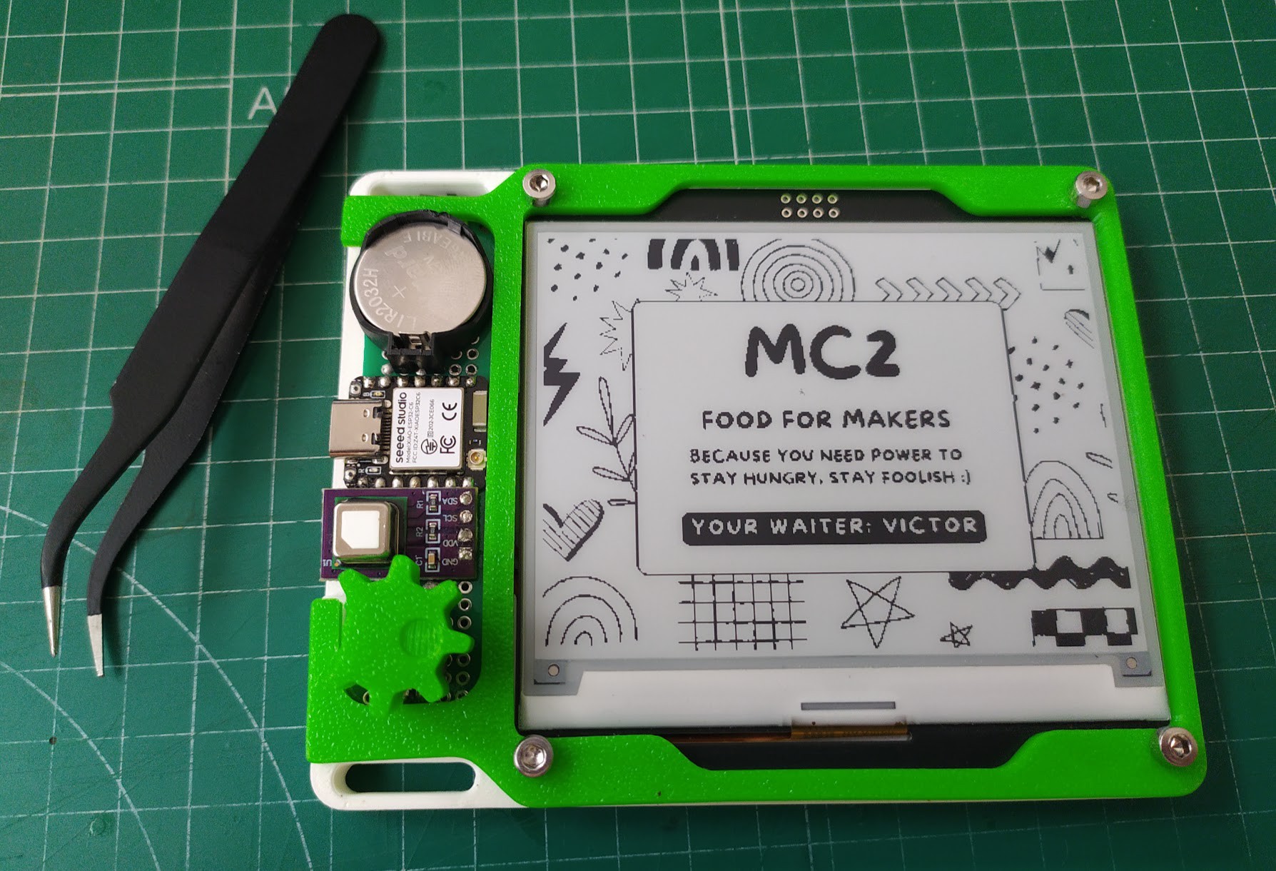
Overview
This is a small handheld instrument that sits somewhere between an environmental meter and a wearable electronic badge. A 4.2-inch, 400x300 pixel e-paper panel fills most of the front face and shows air-quality readings, menu screens, and static badge artwork. A single rotary encoder with an integrated push switch handles all navigation, so the device needs no keyboard, touchscreen, or secondary buttons. A slide switch on the shell cuts battery power completely when the unit is put away.
The design leans hard on low average power. E-paper holds an image with no current draw, so the display only consumes energy during a refresh, and the controller spends most of its time asleep between sensor samples. That combination is what makes a 70 mAh rechargeable coin cell a plausible power source for a device with a 100 mm-class screen — something that would be unworkable with a backlit LCD. The tradeoff is refresh latency measured in seconds rather than milliseconds, which shapes the whole user interface toward discrete pages instead of live-scrolling values.
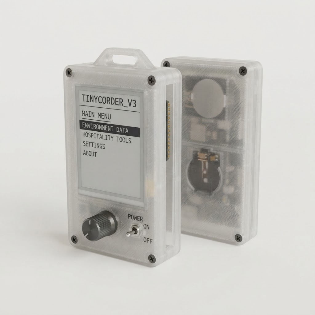
Mechanically the build is a two-part printed chassis closed with four M3x10 screws, with separate printed mounts for the controller, the sensor, and the power switch, plus a printed knob that gives the encoder a usable grip. A lanyard loop lets it hang around the neck, which is the intended way to wear it as a badge. Finished, it is light enough to forget you are carrying it and quiet enough — no fan, no backlight, no beeper — to leave running all day.
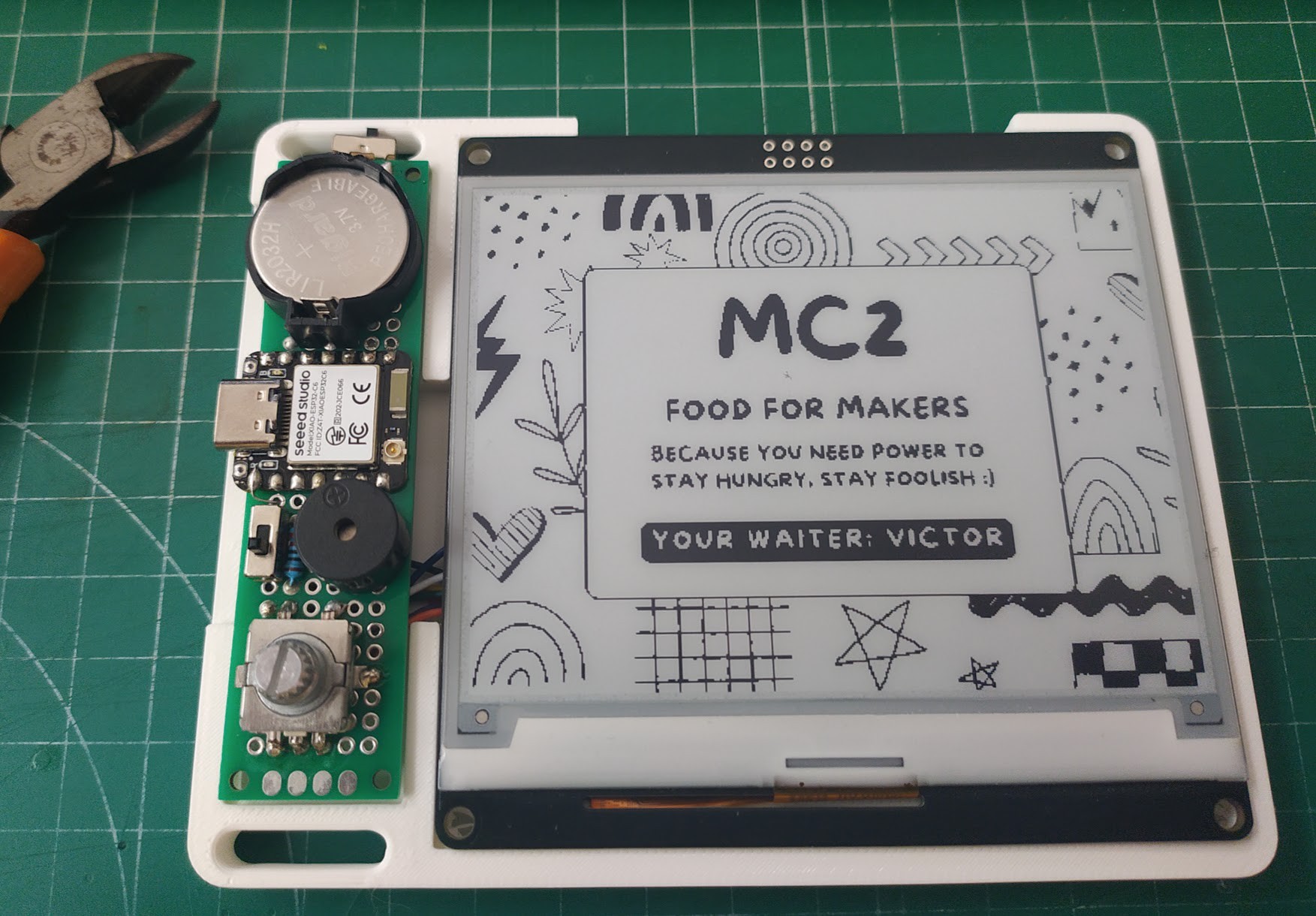
Parts
This parts table is seeded from the Blueprint project.
| Part function | Canonical name | Qty | Type | Size | Est. cost |
|---|---|---|---|---|---|
| Air Quality Sensor | Sensirion SCD40 | 1 | Sensor | 10.1x10.1x6.5mm | $28.00 |
| E-Ink Display | WeAct Studio 4.2-inch 400x300 E-Paper Display Module | 1 | Display | 103x78.5x3mm | $24.00 |
| Main Controller | Seeed Studio XIAO ESP32C6 | 1 | Controller | 21x17.8x3.5mm | $5.20 |
| Rechargeable Battery | 70mAh LIR2032 Rechargeable Coin Cell | 1 | Power | 20x20x3.2mm | $3.50 |
| Neck Carry Loop | Adjustable Breakaway Neck Lanyard with Snap Hook | 1 | Misc | 450x10x2mm | $2.50 |
| Menu Rotary Encoder | Incremental Rotary Encoder with Push Switch | 1 | Module | 15x12x25mm | $2.00 |
| Battery Holder | LIR2032 Coin-Cell Holder | 1 | Power | 24x22x6mm | $1.00 |
| Main Power Switch | Miniature SPST Slide Switch | 1 | Module | 8.5x3.5x3.5mm | $0.75 |
| Chassis Screws | M3 x 10 mm Phillips Pan-Head Machine Screws | 4 | Misc | M3x10mm | $0.32 |
Estimated total for the modeled parts: $67.27.
How It Works
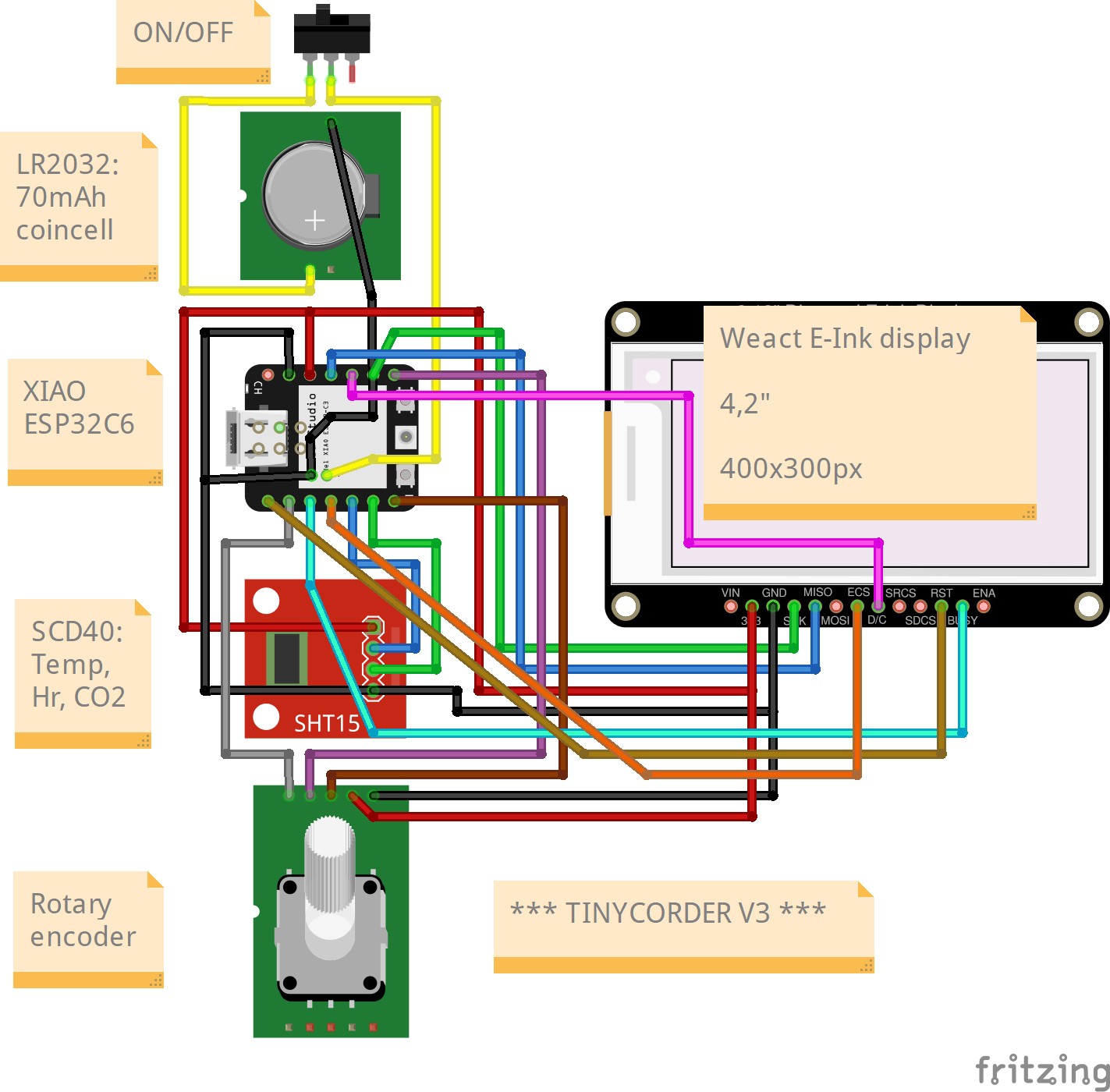
A compact wireless-capable controller board is the only active processor. Power starts at the rechargeable coin cell in its holder; the positive terminal runs through the slide switch and into the board’s battery supply input, while the negative terminal goes straight to ground. The board’s onboard regulator then produces the 3.3 V rail that feeds both the display module and the sensor, so the switch is a true master cutoff for the entire system rather than a standby control. Peak demand is modest — roughly 20 mA during a display refresh and around 18 mA while the sensor is measuring — and those two loads are deliberately never at full draw simultaneously.
The display hangs off the hardware SPI bus: MOSI carries pixel data, SCK the clock, D7 is chip select, D3 selects data versus command, and D2 is the hardware reset. The one signal that flows the other way is BUSY on D1, which the panel asserts for the duration of a refresh. Respecting that line is the single most important detail in the firmware — polling it instead of guessing at delays is what keeps refreshes from tearing or being cut short, and it also tells the controller exactly when it is safe to go back to sleep.
The air-quality sensor sits on I2C using the board’s dedicated SDA and SCL pins, sharing the 3.3 V rail and ground with the display. Because it reports CO2 concentration alongside temperature and humidity from one package, a single bus transaction supplies everything the environmental screens need. The rotary encoder is wired as a simple ground-referenced input: its common pin ties to ground, and quadrature outputs A and B go to D0 and D6 with the push switch on D9, all relying on internal pull-ups and firmware debouncing rather than external RC networks.
Data flow is therefore a loop with a very low duty cycle. The controller wakes on a timer or an encoder event, reads the sensor over I2C, decides whether the on-screen content has actually changed, and only then drives an SPI refresh; if nothing changed it goes straight back to sleep and the panel keeps displaying the last image for free. Because the current firmware also carries custom menu content — settings, an information page, and an order-taking screen set aimed at hospitality use — the same display pipeline serves both live measurements and purely static pages.
Build Steps
-
Print and prepare the enclosure. Run the two chassis halves and the encoder knob in PLA, with the knob at about 30% infill so it stays stiff under thumb pressure, and print the three internal mounts for the controller, sensor, and power switch in PETG with four perimeters — they carry the screw and press-fit loads. Remove supports and deburr the display window, encoder hole, switch cutout, sensor vent, and lanyard slot before any electronics go near them.
-
Dry-fit everything before soldering. Drop the mounts into the bottom half, confirm the four M3 screw bosses line up between halves, and check that the display sits flush against the window without bowing. Fixing a tight cutout now takes a knife; fixing it later means desoldering a harness.
-
Build the power path first. Solder the holder’s positive terminal through the slide switch to the controller’s battery supply input and the negative terminal directly to controller ground. Leave the cell out. With the battery installed and the switch on, verify roughly 3.6 V at the switch output and a clean 3.3 V rail on the board before anything else is connected — this is the one check that protects every downstream part.
-
Wire the three peripheral harnesses. Take 3.3 V and ground to both the display and the sensor, then run MOSI, SCK, and D7/D3/D2 to the panel’s data, clock, chip-select, data-command, and reset pins, with the panel’s BUSY output back to D1. Take SDA and SCL to the sensor. Wire the encoder’s common to ground and A, B, and the push switch to D0, D6, and D9. Insulate and label each harness — once the shell closes, the bundles are indistinguishable.
-
Bring up subsystems one at a time. Confirm continuity and check for shorts between the rails, then load a display-only sketch with the pin map above and run a full refresh, watching BUSY behave. Next scan I2C for the sensor and sanity-check its CO2, temperature, and humidity output against ambient expectations. Finally test the encoder for direction, missed detents, and switch bounce, tuning the debounce interval until single clicks register once.
-
Load the integrated firmware and measure current. With all three subsystems working together, check both sleep and active draw. Against a 70 mAh cell, sleep current is the number that decides runtime — if it is higher than expected, look for a peripheral left powered or a pin held in a state that defeats deep sleep.
-
Assemble the stack. Seat and align the display behind the top window, fit the encoder through its opening and press on the knob, then install the controller, sensor, and switch in their PETG mounts in the bottom half. Mount the holder and insert the cell with polarity double-checked — a reversed coin cell is an expensive mistake here.
-
Close and finish. Route the wiring clear of the screw posts and the shell seam, add strain relief where harnesses cross the hinge line, then close the chassis and tighten the four M3 screws evenly in a cross pattern to avoid warping the display window. Thread the lanyard through the loop and run a full handheld test: switch on, cycle every menu, confirm sensor readings update, and verify the panel refreshes cleanly while the unit is being moved.
See the complete build steps in Blueprint.
Notes
The dominant tradeoff is refresh speed against battery life, and it should be embraced rather than fought. Full-panel refreshes on a 400x300 e-paper module are slow and visually noisy, so design menus as pages that change on a deliberate encoder click instead of trying to animate values; partial-update modes help but accumulate ghosting, which means scheduling an occasional full refresh to clear the panel. On calibration, the CO2 sensor needs warm-up time before its readings settle, and its self-calibration behavior assumes periodic exposure to fresh outdoor air — a device that lives permanently in one closed room will drift, so plan to either air it out regularly or force a reference calibration. Sensor placement matters too: mounting it near the vent and away from the controller keeps self-heating from biasing the temperature and humidity channels.
On safety and practicality, treat the rechargeable coin cell with respect. It is a lithium cell in a rigid printed shell, so keep the holder terminals from shorting against wiring, never pinch the cell during assembly, and confirm polarity before the first power-up. The 70 mAh capacity is genuinely small — it works only because the sleep current is low, so any firmware change that keeps a peripheral awake will collapse runtime dramatically, and it is worth re-measuring sleep draw after every significant firmware revision. The build has obvious room to grow: the I2C bus has capacity for additional sensors at the same 3.3 V, the printed mounts are easy to revise for new modules, and because the display pipeline already handles static pages, adding new screens is mostly a content problem rather than a hardware one. The current menu structure is intentionally provisional and expected to be reorganized as more sensing is added.