
CoreXY Pen Plotter with an Automatic Five-Tool Changer
A compact five-tool pen plotter with an automatic toolchanger, kinematic tool coupling, RFID-stored tool offsets, and self-calibrating XYZ alignment.
Overview
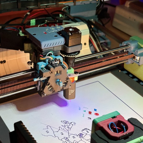
This is a small desktop pen plotter that swaps its own pens. Five lightweight tools sit in a row of docks along the back of the machine; the toolhead drives up to a dock, engages a rotating key, lifts the tool off its cradle, and carries on drawing. Each tool carries an RFID tag holding its own XYZ offset and identifier, so the machine knows where the nib actually is the moment it picks the tool up. The result is multi-pen artwork — line weights from 0.03 mm to 0.7 mm, text down to about 1.5 mm tall — without a human standing by to change pens and re-zero between colors.
The approach is deliberately salvage-first. The motion platform is a CoreXY frame built around ground rods, linear bearings, belts, idlers and stepper motors reclaimed from a retired FDM 3D printer, with an 8-bit controller board and a single-board host running standard motion-control firmware. Everything structural is 3D printed. What makes it interesting is not the gantry but the coupling: a three-point kinematic mount, actuated by a very low-torque miniature linear stepper turning a key through a rack and gear. Because the motor can barely produce any torque, repeatability has to come from geometry and low friction rather than clamping force — which drives most of the design decisions downstream.
The finished machine plots on A5 paper held flat by a magnetic bed. A removable calibration bed swaps in over the same magnetic mount: a resistive touch panel that the toolhead probes directly, letting the machine measure each tool’s XY and Z offset against a reference pen and write the result back to that tool’s tag. Docking and undocking are reliable enough for unattended multi-tool plots, and dock presence switches confirm every pick and place.
Parts
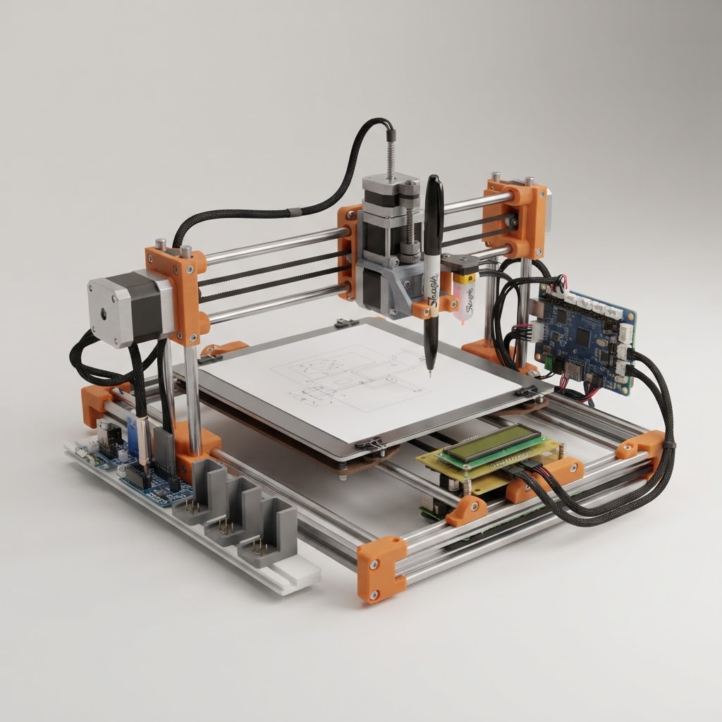
This parts table is seeded from the Blueprint project.
| Part function | Canonical name | Qty | Type | Size | Est. cost |
|---|---|---|---|---|---|
| Optional Force-Sensor Array | Interlink FSR 400 8x4 Sensor Array | 1 | Sensor | 80x40x1mm | $240.00 |
| Klipper Host | Raspberry Pi 4 Model B | 1 | Controller | 85x56x17mm | $60.00 |
| Bed Mesh Probe | Antclabs BLTouch | 1 | Sensor | 37x18x12mm | $40.00 |
| Main Motion Controller | Melzi V2.0 ATmega1284P Controller | 1 | Controller | 210x50x15mm | $32.00 |
| Main Regulated Supply | Mean Well LRS-150-12 | 1 | Power | 159x97x30mm | $30.00 |
| Optional Dock-Centering Sensor | ST VL53L5CX Time-of-Flight Sensor Breakout | 1 | Sensor | 25x18x5mm | $25.00 |
| Tool RFID Reader | USB RFID Reader Module (frequency matched to tool tags) | 1 | Sensor | 104x68x12mm | $25.00 |
| Tool-Lock Actuator | Miniature Captive Linear Stepper Motor | 1 | Actuator | 15x15x35mm | $24.00 |
| Five-Volt Axis Supply | Pololu D24V50F5 5V Step-Down Regulator | 1 | Power | 26x18x9mm | $20.00 |
| Toolhead Z Motor | NEMA 8 Bipolar Stepper Motor | 1 | Actuator | 20x20x30mm | $19.00 |
| A5 Magnetic Paper Bed | Flexible Magnetic Build Plate | 1 | Structural | 240x180x3mm | $18.00 |
| Paper Bed Support Plate | 6061 Aluminum Sheet | 1 | Structural | 250x190x3mm | $18.00 |
| Touch-Bed USB Controller | ESP32-2432S028R 2.8-inch Cheap Yellow Display Board | 1 | Controller | 86x50x14mm | $18.00 |
| CoreXY A Motor | NEMA 17 Bipolar Stepper Motor | 1 | Actuator | 42x42x40mm | $14.00 |
| CoreXY B Motor | NEMA 17 Bipolar Stepper Motor | 1 | Actuator | 42x42x40mm | $14.00 |
| Controller (Optional Touch ADC, Optional FSR ADC, Optional Sensor-Bed Power) | Raspberry Pi Pico RP2040 | 3 | Controller | 51x21x4mm | $12.00 |
| CoreXY Idler Set | GT2 20-Tooth Smooth Idler Pulley, 3 mm Bore | 8 | Mechanism | 18x18x9mm | $12.00 |
| Toolhead Cable Chain | 10x10 mm Openable Drag Chain | 1 | Mechanism | 500x18x15mm | $12.00 |
| Lock PTFE Lubricant | Super Lube PTFE Dry Film Lubricant | 1 | Misc | 150x45x45mm | $10.00 |
| Dock Switch Expander | Adafruit MCP23017 I2C GPIO Expander Breakout 5346 | 1 | Module | 51x25x5mm | $9.00 |
| Left 8 mm Frame Rod | Hardened Chrome Linear Shaft | 1 | Structural | 360x8x8mm | $9.00 |
| Right 8 mm Frame Rod | Hardened Chrome Linear Shaft | 1 | Structural | 360x8x8mm | $9.00 |
| Calibration Touch Surface | 2.8-inch 4-Wire Resistive Touch Panel | 1 | Sensor | 70x50x1mm | $8.00 |
| Removable Panel Connector | Magnetic Pogo-Pin Connector | 1 | Module | 20x8x4mm | $8.00 |
| Tool Pogo Interface | Mill-Max Spring-Loaded Pogo Contact Set | 1 | Module | 12x8x10mm | $8.00 |
| RFID Tag (Tool 1, Tool 2, Tool 3, Reference Tool T4, Tool 5) | Rewritable Passive RFID Tag | 5 | Module | 25x25x1mm | $7.50 |
| Front 6 mm Y Guide | Hardened Chrome Linear Shaft | 1 | Mechanism | 260x6x6mm | $7.00 |
| Rear 6 mm Y Guide | Hardened Chrome Linear Shaft | 1 | Mechanism | 260x6x6mm | $7.00 |
| Switch (X Homing, Y Homing, Dock 1 Presence, Dock 2 Presence, Dock 3 Presence, Dock 4 Presence, Dock 5 Presence) | KW12-3 Lever Microswitch | 7 | Sensor | 20x10x6mm | $7.00 |
| Z Screw Coupler | 3 mm to 3 mm Flexible Shaft Coupler | 1 | Mechanism | 20x12x12mm | $6.00 |
| CoreXY Belt A | GT2 Open Timing Belt 6 mm | 1 | Mechanism | 1200x6x1.4mm | $5.00 |
| CoreXY Belt B | GT2 Open Timing Belt 6 mm | 1 | Mechanism | 1200x6x1.4mm | $5.00 |
| M3 Assembly Screws | M3 Socket-Head Machine Screws | 60 | Misc | M3x12mm | $4.80 |
| M3 Heat-Set Inserts | M3 Brass Heat-Set Threaded Inserts | 32 | Misc | M3x5mm | $3.84 |
| Front Toolhead Bearing | LM6UU Linear Bearing | 1 | Mechanism | 19x12x12mm | $2.00 |
| Left Frame Bearing | LM8UU Linear Bearing | 1 | Mechanism | 24x15x15mm | $2.00 |
| Rear Toolhead Bearing | LM6UU Linear Bearing | 1 | Mechanism | 19x12x12mm | $2.00 |
| Resistive Touch Controller | XPT2046 Touch Controller | 1 | Sensor | 7x5x1mm | $2.00 |
| Right Frame Bearing | LM8UU Linear Bearing | 1 | Mechanism | 24x15x15mm | $2.00 |
| Kinematic Contact Screws | M3 Stainless Cup-Point Set Screw | 3 | Misc | M3x12mm | $0.54 |
| M3 Z Lead Screw | M3 Fully Threaded Socket-Head Screw | 1 | Mechanism | M3x35mm | $0.25 |
| BLTouch Probe OR Transistor | 2N3904 NPN Transistor | 1 | Module | 5x5x5mm | $0.15 |
| Touch Probe OR Transistor | 2N3904 NPN Transistor | 1 | Module | 5x5x5mm | $0.15 |
| Z Lead Nut | M3 Hex Nut | 1 | Misc | M3x2.4mm | $0.05 |
Estimated total for the modeled parts: $758.28.
How It Works
Motion is CoreXY: two fixed steppers drive a pair of 6 mm belts so the toolhead moves in X and Y with no motor mass riding on the gantry. The Z axis lives on the toolhead itself — a small stepper turns an M3 screw against a captive nut to raise and lower the tool. Because the screw sits on one side of the rider, the carriage is guided by a triangular slide layout borrowed from optical-drive mechanisms; without it, the rider tilts and jams. That axis runs at roughly 0.03 mm per rotation with microstepping disabled, since the 8-bit controller cannot generate steps fast enough to drive it microstepped. It is slower than a belted Z but backlash-free, and pen up/down/travel are just three fixed heights (about 0.2 mm, 5 mm, and 7 mm) issued through an overridden move macro.
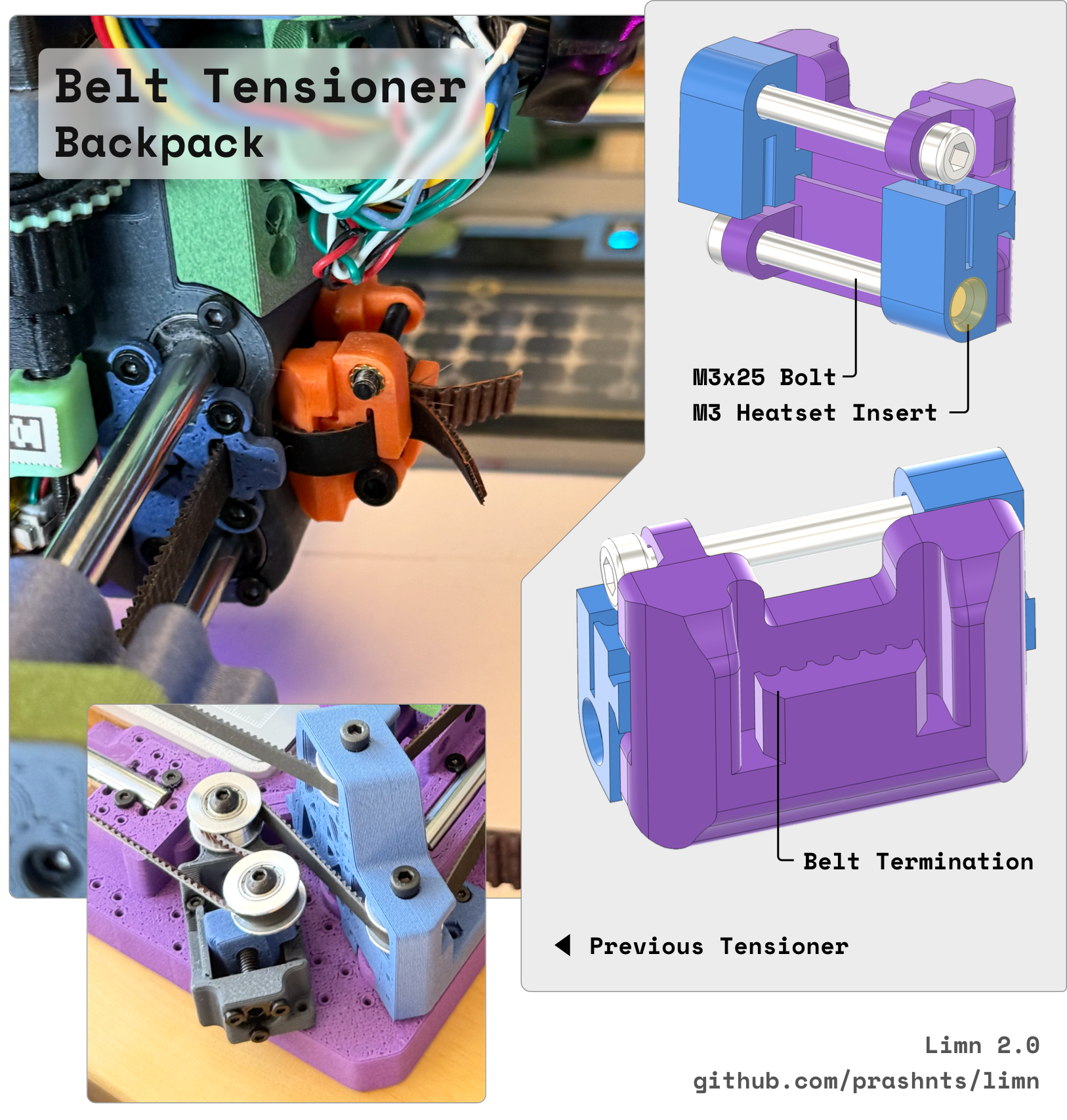
Tool docking is a three-point kinematic coupling: three cup-point set screws on the tool seat into matching features on the carriage, and a rotating key — turned by a rack-and-pinion off a tiny captive linear stepper — pulls them together. The actuator’s torque is very low, so the whole machine has to be tight and smooth for the coupling to seat: slack belts alone were enough to make docking unreliable, which is why belt tension is taken up by a small printed tensioner at the toolhead with captive clip tracks. A dry PTFE film on the lock mechanism made a noticeable difference. A lever microswitch under each cradle reports whether a tool is present, so the firmware can tell a successful pick from a failed one, and a manual recovery wheel and levers let you move the axes by hand when things go wrong.
Tool identity and calibration ride on RFID. A USB reader at a fixed read station on the frame scans the tag on the docked tool; a firmware extension runs a shell helper, returns the XYZ offset and tool name in a delimited string, stores them as saved variables, and applies them with a gcode offset. Offsets are applied selectively — only moves tagged as drawing or travel get the offset, so physical operations like docking and tag reading always run in true machine coordinates. Offsets are measured by probing: the removable resistive touch panel emits a short 3.3 V pulse on touch, which is OR’d with the Z probe’s signal through a pair of NPN transistors into a single probe endstop input, so bed meshing and probing work unchanged whichever sensor fires. The machine meshes the panel and the paper, probes a reference tool at several sample points, then probes each remaining tool at points from that set and subtracts to get its XYZ offset before writing it back to the tag. Measured repeatability is around 0.2 mm, which is adequate for 0.5 mm pens.
Build Steps
-
Print and prepare the parts. Print the frame brackets and motor mounts, the toolhead carriage and belt tensioner with its clip tracks, the kinematic coupling and lock mechanism, the dock rail with five cradles and switch brackets, the pen bodies, and the electronics and calibration-bed housings. Print the tensioner body at an angle so the small screw holes get some layer strength, and chamfer the clip tracks so tensioned belt clips can be inserted. Install roughly 32 M3 heat-set inserts, then deburr everything and test-fit the rods and bearings before assembly.
-
Build the frame and CoreXY motion. Square the corner brackets onto the aluminum base plate and fit the two 8 mm frame rods, then the 6 mm Y guides, bearings and toolhead carriage. Mount the two motors and eight idlers, route both belts, and tension them at the toolhead backpack. Do not treat tension as a detail — loose belts are the single most common cause of docking failures later, and an inline moving tensioner is a bad idea here because it wears the belt.
-
Assemble the Z lift and tool lock. Fix the M3 screw to its bracket with a nut and thread-locker, couple it to the Z motor, and fit the triangular rider so it stays level across its travel. Install the three cup-point contact screws on the coupling, then the linear lock actuator, rack, gear and rotating key. Apply dry PTFE film to the lock. Confirm by hand that the key rotates freely and that the coupling seats without the motor having to fight anything.
-
Wire power, motors and sensors. Bring in mains safely to the 12 V supply, feed the 5 V step-down regulator from it, and supply the host and the two modified 5 V axis rails. Build four labeled stepper harnesses. Wire the X and Y homing switches to the controller endstops and the five dock switches to the I2C expander on the host. Build the two-transistor OR gate combining the touch-panel pulse and the Z probe into the single probe endstop input, and check it fires on either source before powering the motors. Route the moving harnesses through the drag chain with strain relief at both ends.
-
Bring up the electronics under current limit. Verify the 12 V, 5 V and 3.3 V rails before connecting anything expensive. Flash the motion firmware and confirm USB communication with the controller. Check stepper phase order and direction at conservative current limits, then test homing and fail-safe switch states, scan the I2C bus for the expander and toggle all five dock inputs, and confirm the RFID reader identifies each of the five tags.
-
Install the beds, docks and tools. Fit the magnetic A5 paper bed, mount the adjustable dock rail with its five cradles, and add the dock switches. Assemble the pen bodies with adjustable collets and fit their RFID tags — recess the tag, and shape the cradle around where the chip sits, or the tool holder will rub the tag apart over repeated docking cycles. Mount the electronics enclosures, the fixed RFID read station, the Z probe on the toolhead, and the removable touch panel on its magnetic pogo connector.
-
Calibrate the machine. Set the Z rotation distance (around 0.03 mm/rotation with microstepping off), tune the dock approach coordinates, and mesh both the touch panel and the paper area with the Z probe. Then run the tool calibration cycle: pick the reference pen, probe the panel at three locations to get the transform, collect the sample set, and for each remaining tool probe, subtract, and write the XYZ offset to its tag. Roughly ten units of touch-panel displacement corresponds to 1–2 mm of toolhead movement — useful when sanity-checking the transform.
-
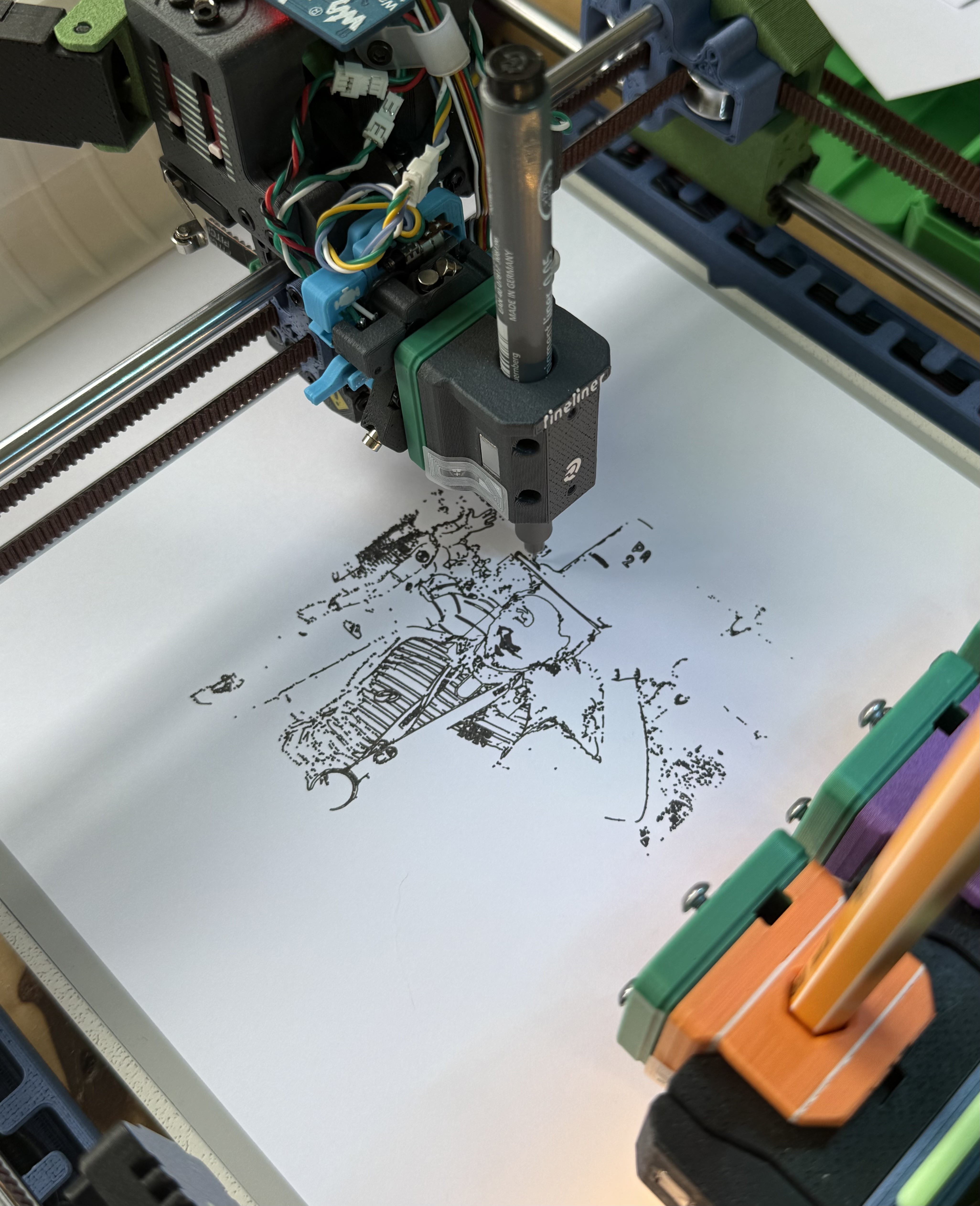
Verify with a real plot. Have each tool draw a segment of a continuous alignment line and inspect the joins by eye; misalignment shows up immediately as a step. Then run a full multi-tool plot end to end, watching that every pick and place is confirmed by the dock switches.
See the complete build steps in Blueprint.
Notes
The central tradeoff is torque versus mass. The locking actuator is genuinely weak, which limits this design to lightweight tools but also forces the precision that makes it work — every source of wobble, friction or belt slack shows up directly as a failed dock. Expect to chase that: a month of intermittent docking trouble traced back to belt tension, not to the coupling geometry. The electrical tool interface is the weakest part as built. Three contacts (VCC, GND, and one GPIO) are carried through the coupling screws, but contact resistance through the screws is too high to be useful; spring pins are the better path. Spring pins bring their own problem — they inject noise, and leaving them permanently powered is unwise, so gate their supply on detecting that the bed or tool is actually present. Treat the shell-execution hook used for RFID reads as a real security caveat: any gcode you run can invoke it, so only plot files you trust.
Worthwhile refinements: recess the RFID tags inside the tool bodies from the start rather than surface-mounting them, since retrofitting after printing twenty tools is unappealing. A force-sensor array can push XY alignment past what the resistive panel gives, though 0.2 mm was already sufficient for 0.5 mm pens and the panel handles Z well. A time-of-flight ranging module looked viable for automatically finding dock center parameters — a tedious manual process — but needed shape changes or retroreflective patches on the holders to be dependable, and was set aside. Add a screen protector layer over the touch panel and rotate probe locations to spread wear. Finally, if you want more than five tools, add extra tool entries in the slicer and insert a pause on the transition so you can swap the physical set by hand.