
Compact Alphanumeric Split-Flap Character Module
A mostly 3D-printed split-flap character module with 38 flaps, a continuous-rotation servo, reflective code-wheel homing, and an addressable bus for chaining units.
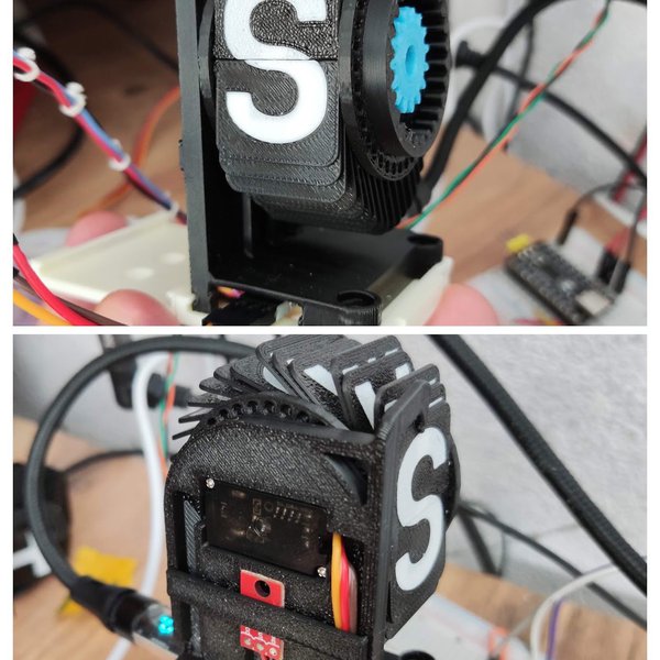
Overview
This build is a single split-flap character cell that can show the full English alphabet, the digits, a space, and one extra symbol across 38 flaps. Each cell is self-contained: it carries its own small microcontroller, its own drive motor, and its own position sensor, and it listens on a shared four-wire bus for the character it should display. Chain several cells together and a single bus controller can drive a whole word.
The design goal was compact, cheap, and mostly reliable, with a little jankiness accepted in exchange for printability. Almost every structural part comes off the printer: the frame, bezel, rear cover, brackets, electronics trays, the 38-position flap carrier, the code wheel, and the flaps themselves. The only bought items are a continuous-rotation micro servo, a reflective optical sensor breakout, a tiny microcontroller board, a passive bus distribution board, and a dozen M2 screws. The modeled bill of materials lands around sixteen dollars per cell.
Positioning is open-loop drive with closed-loop confirmation. There is no stepper and no encoder. A 360-degree servo spins the carrier continuously while the reflective sensor counts painted tick marks on a code wheel that turns with it, so the controller always knows how many positions it has advanced and where home is. That keeps the mechanism cheap and keeps the part count low.
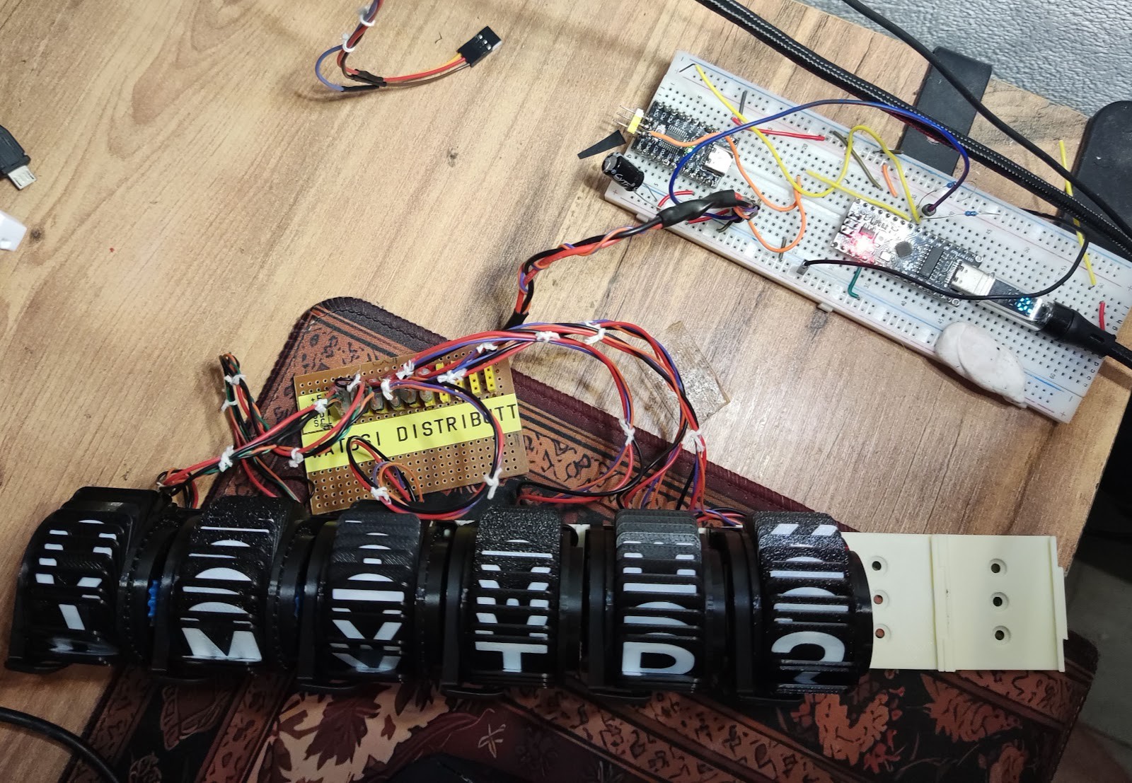
Finished, a cell is bigger than the word “mini” suggests. Six units side by side already make an intimidating object, and the wiring between them is the part that eats the most bench time.
Parts
This parts table is seeded from the Blueprint project.
| Part function | Canonical name | Qty | Type | Size | Est. cost |
|---|---|---|---|---|---|
| Display Bus Controller | Arduino Nano 5V (ATmega328P) | 1 | Controller | 45x18x8mm | $5.00 |
| Character Drive Servo | MG90S 360 Degree RC Micro Servo | 1 | Actuator | 22.8x12.2x28.5mm | $4.50 |
| Character Controller | V1772 CH32V003F4P6 Development Board | 1 | Controller | 23x18x4mm | $2.00 |
| Code Wheel Sensor | QRE1113 Analog Sensor Module (3-resistor module) | 1 | Sensor | 25x15x5mm | $2.00 |
| I2C Power Distribution Board | 4-Strip 5V/GND/SDA/SCL Distribution Board | 1 | Module | 50x20x2mm | $1.50 |
| White Tick Paint | Apple Barrel Gloss White Acrylic Paint | 1 | Misc | 38x38x38mm | $0.50 |
| Frame Fasteners | M2 x 8mm Phillips Pan Head Machine Screws | 12 | Misc | M2x8mm | $0.48 |
Estimated total for the modeled parts: $15.98.
How It Works
Control is split into two levels. A 5 V bus controller board holds the message and acts as the I2C master on its A4 and A5 pins. Every character cell has its own microcontroller listening at a unique I2C address on its PC1 and PC2 pins. The master sends a cell a target character; the cell figures out how far to turn and does the turning itself. I2C was chosen over multiple serial links mainly because the star topology comes for free and because everything on the bus already runs at 5 V, which removes a level-shifting headache.
Inside a cell, the microcontroller drives the continuous-rotation servo with a single PWM line and watches the reflective sensor’s analog output on an ADC pin. The code wheel rides coaxially with the flap carrier and carries 38 white tick marks, one per flap position, with one deliberately thicker tick marking home. As the carrier turns, each tick produces a reflectance peak; counting peaks converts continuous rotation into discrete character positions, and the wide home tick lets the cell re-zero itself.
The detection algorithm tracks a running minimum and maximum of the sensor signal rather than using a fixed threshold, which is what makes the thing tolerant of print defects and uneven paint. A tunable tracking divisor sets how quickly those tracked peaks decay back toward the middle. Larger values decay more slowly and hold a firmer threshold. This parameter turned out to be the single most useful knob for tuning, because the variation between supposedly identical cells is much larger than expected even with motors out of the same bag.
Power and signal distribution are deliberately dumb. A passive board carries four strips, 5 V, ground, SDA, and SCL, and every cell taps all four. Each cell budgets roughly 500 mA on the 5 V rail for its controller and servo, with the optical sensor drawing about 10 mA. Because there are no custom PCBs, all of this is discrete wire, which is why harness lengths are measured and braided rather than left loose.
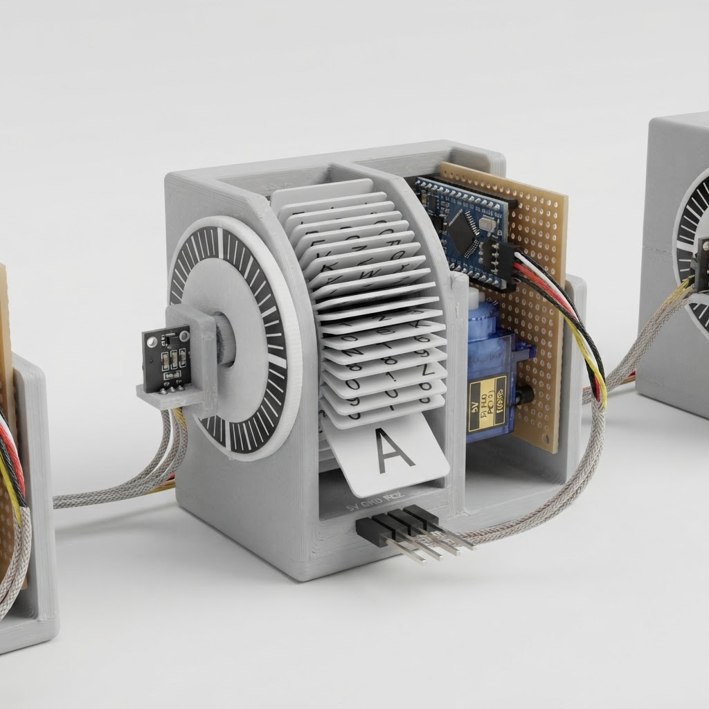
Build Steps
-
Print the structural set. Run the frame, bezel, rear cover, servo and sensor brackets, controller tray, and the two electronics mounts in PETG. Print the flap carrier at high strength since it takes all the rotational load, and print the code wheel and the 38 flaps with fine layers so the tick edges and flap pivots stay crisp. Deburr every pivot, slot, and axle seat, then check that each flap swings freely before it goes anywhere near the carrier.
-
Paint and dry-fit the code wheel. Lay down 38 evenly spaced white tick marks, making the home tick noticeably thicker than the rest. Let the paint cure fully. Gloss white acrylic reads much brighter to the sensor than white filament does, so paint the ticks even if your filament is already white. Dry-fit the wheel on the carrier hub and the carrier axle in the frame before committing to assembly.
-
Build and verify the harness. Cut, braid, and label four-wire runs for 5 V, ground, SDA, and SCL between the distribution board and both controllers. Take the 5 V and ground taps out to the servo and the sensor, then run the controller’s PWM line to the servo signal lead and the sensor’s analog output to the ADC pin. Insulate joints, add strain relief, and ring out every rail and signal for shorts and continuity. This step takes far longer than it sounds.
-
Power up without the motor. Leave the servo disconnected, energize the 5 V system, and confirm regulated voltage and a shared ground at every board. Flash the bus controller, then flash the cell controller with its I2C address, bus pins, ADC pin, and servo PWM pin set. Scan the bus and clear any addressing, pull-up, or wiring fault before the actuator is allowed to move.
-
Characterize the sensor. Turn the carrier by hand and log the analog level over bare code-wheel material and over the painted ticks. Record the swing and set a detection threshold with real margin. Tune the tracking divisor here as well, because each cell will want a slightly different value even with identical firmware.
-
Wake the servo carefully. Before coupling to the carrier, exercise the servo over limited travel, establish safe pulse endpoints, and confirm the direction of rotation. Then couple it, implement homing from the wide tick, and command a full 38-position index sweep to prove the count stays honest over a complete revolution.
-
Assemble the cell. Load all flaps into their labeled carrier slots and spin the wheel to confirm nothing binds. Press the code wheel onto the hub, seat the axle in the frame supports, and screw the servo, sensor, and controller into their brackets and tray with the M2 hardware. Align the servo drive to the carrier and position the sensor bracket for a clean reflectance signal.
-
Close it up. Mount the distribution board and bus controller to the rear cover, route the braided wiring clear of the rotating carrier, and fasten the bezel and rear cover to the frame. Finish with a homing run and a full character cycle to confirm nothing shifted during closeout.
See the complete build steps in Blueprint.
Notes
The biggest lesson is that identical cells are not identical. Same firmware, same motors from the same bag, same print settings, and the sensor behavior still varies enough that per-cell tuning parameters are not optional. Building in a tunable threshold and a tunable decay rate from the start pays for itself the first time you assemble more than two units. Print defects in the tick marks are survivable if the detection algorithm tracks running peaks rather than comparing against a fixed level, and touching up dull ticks with gloss white paint gives noticeably better contrast than relying on white filament alone.
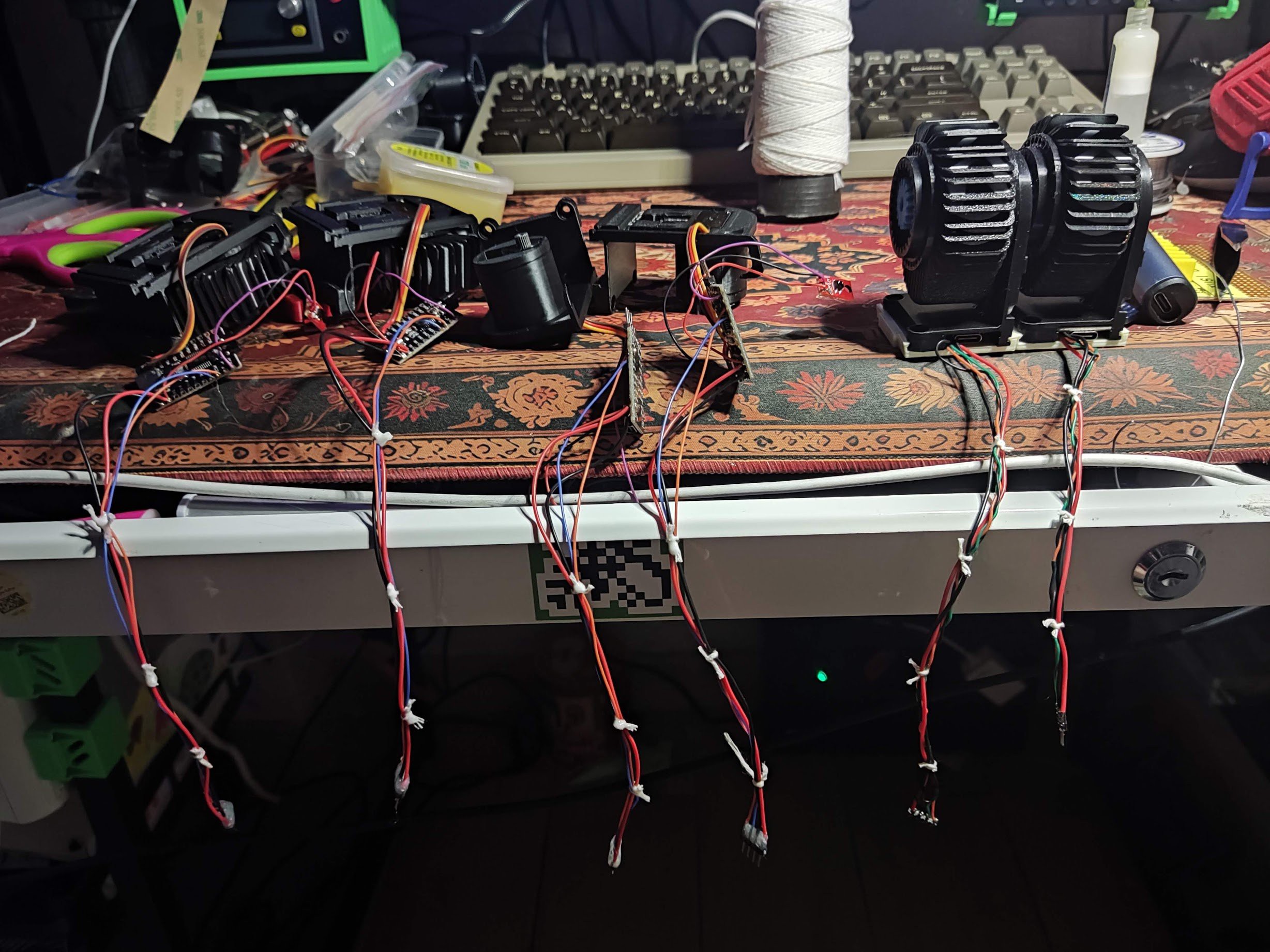
Two tradeoffs are worth naming. Skipping custom circuit boards keeps cost and lead time down but converts the project into a large amount of hand wiring, and that wiring dominates the build time once you pass a few cells. Choosing I2C over multiple serial links buys star topology and a shared 5 V domain, at the cost of giving up the tidy single-connector scheme that a serial link would allow; whether the bus can be remapped onto the controller’s serial pins is worth checking, since it would save considerable soldering. Also plan the physical scale honestly before committing. Cells that sound small on paper add up quickly, and an eight- or ten-character display needs somewhere to live.