
Portable Retro Terminal with a Moving Camera and Rear Status Display
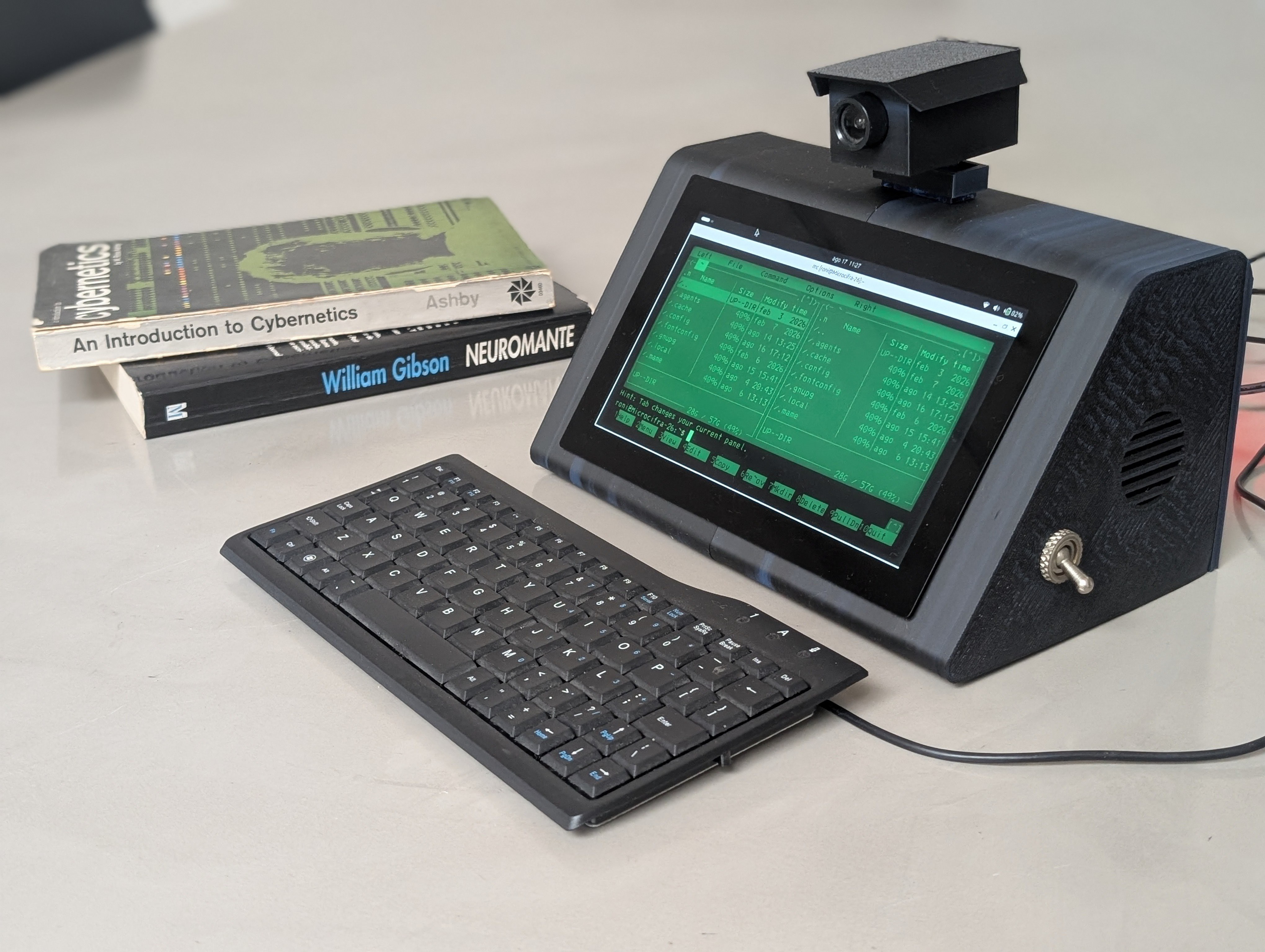
A portable computer pairs a seven-inch screen with physical controls, a servo-mounted camera, and a rear light matrix in a printed enclosure.
Overview
This portable terminal combines a desktop computing environment with controls and peripherals that respond directly to the user. A seven-inch screen forms the front face, a small camera moves on a servo bracket, and a rear-facing light matrix can show short status messages. A buzzer and side-mounted speaker provide simple alerts and application audio.
The design divides the work between a main computer and an integrated microcontroller. The computer handles applications, camera input, storage, and sound; the microcontroller handles the joystick, dial, toggle switch, camera positioning, and rear display. This separation keeps physical interaction independent of desktop application timing.
A housing assembled from several printed sections gives the device its retro proportions while making the electronics accessible. Camera alignment, display ribbon clearance, battery placement, and speaker access all compete for space, so the enclosure should be fitted around measured parts rather than nominal module dimensions.
Parts
This parts table is seeded from the Blueprint project.
| Part function | Canonical name | Qty | Type | Size | Est. cost |
|---|---|---|---|---|---|
| Main Controller | LattePanda IOTA | 1 | Controller | 70x70x10mm | $220.00 |
| Main Display | 7 inch EDP Display | 1 | Display | 165x100x5mm | $60.00 |
| UPS Module | 18650 Battery UPS Shield | 1 | Power | 100x50x20mm | $25.00 |
| CCTV Camera | USB Camera Module | 1 | Sensor | 30x30x20mm | $15.00 |
| Rear LED Matrix | SainSmart MAX7219 8x8 LED | 1 | Display | 32x32x15mm | $8.00 |
| Audio Speaker | 3W Micro Speaker | 1 | Actuator | 40x40x10mm | $5.00 |
| Navigation Joystick | KY-023 Joystick | 1 | Sensor | 35x25x30mm | $5.00 |
| Camera Servo | SG90 Micro Servo | 1 | Actuator | 23x12x29mm | $4.00 |
| Audio Amplifier | PAM8403 3W Module | 1 | Module | 20x15x5mm | $3.00 |
| Mechanical part | M3 Standoff and Screw Set | 20 | Misc | M3x10mm | $3.00 |
| Control Pot | 10k Potentiometer | 1 | Sensor | 15x15x20mm | $2.00 |
| Toggle Switch | SPST Toggle Switch | 1 | Sensor | 10x10x25mm | $2.00 |
| Mechanical part | M3 Threaded Inserts | 16 | Misc | M3x4mm | $1.60 |
| Alert Buzzer | Active Piezo Buzzer | 1 | Actuator | 12x12x10mm | $1.00 |
Estimated total for the modeled parts: $354.60.
How It Works
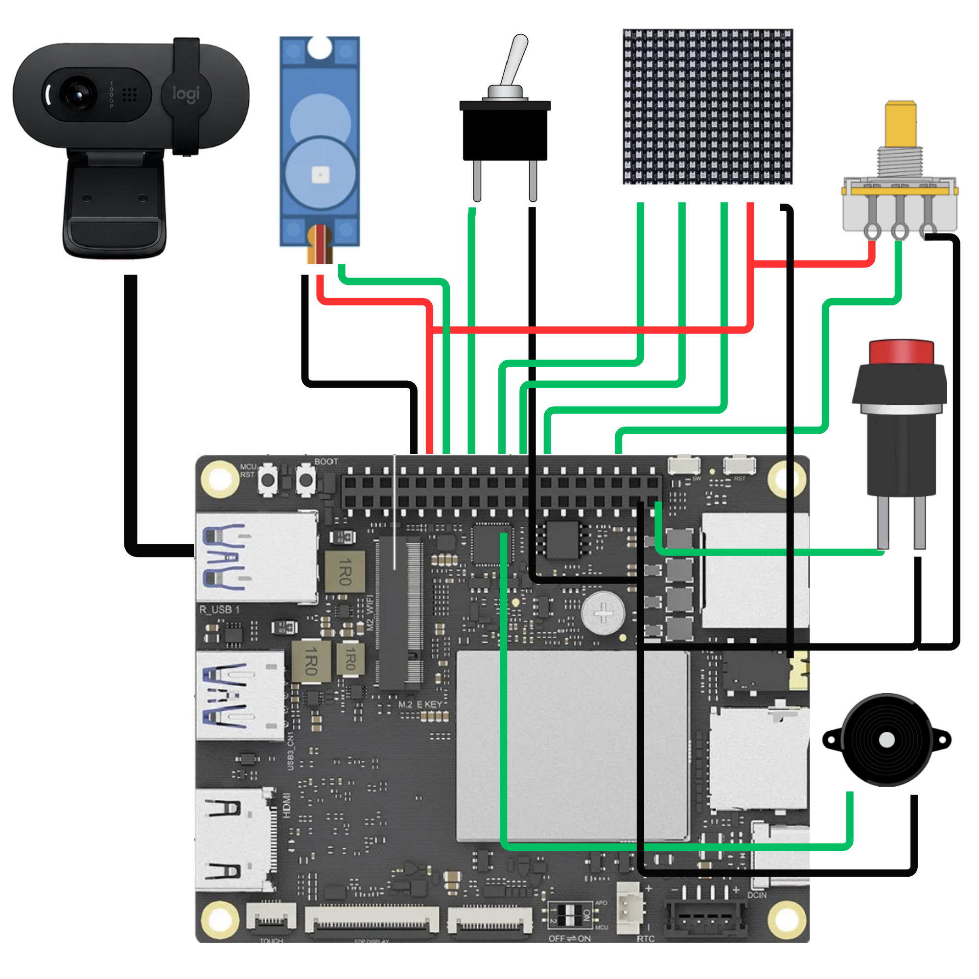
The main processor connects to the front display through its display ribbon and to the camera over USB. Analog audio feeds an amplifier before reaching the speaker. The camera also introduces another audio input device, so the operating system must be able to enumerate both sound interfaces without conflicting fixed device assignments.
The microcontroller uses GP0 for the camera servo, GP1 for the toggle switch, GP2 through GP4 for the rear matrix’s serial interface, GP7 for the joystick switch, GP10 for the buzzer, and GP11 for the rotary input. GP26 and GP27 read the joystick axes. Confirm those assignments against the firmware, along with input voltage limits and the pull-up arrangements for switches.
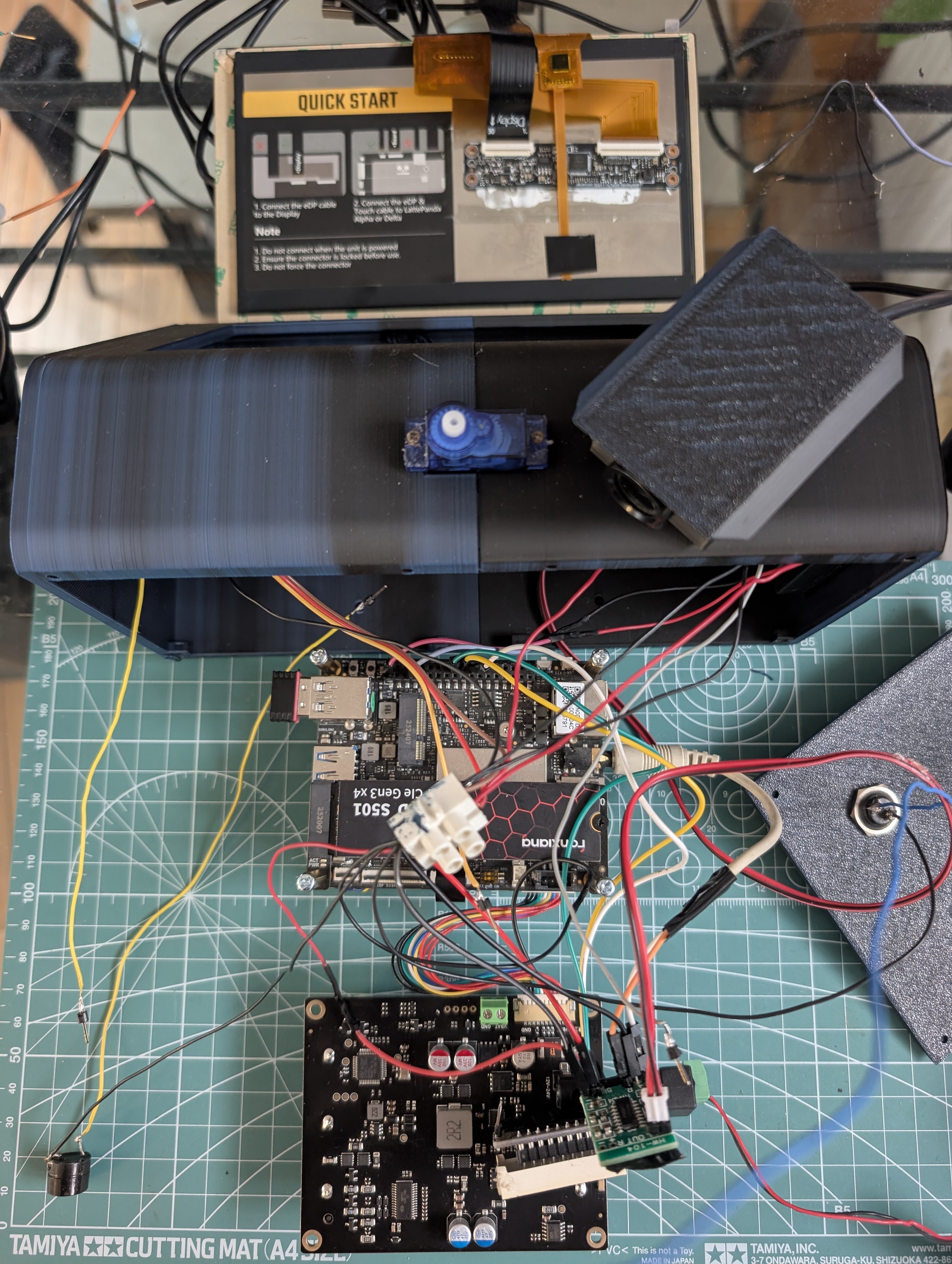
A battery-backup module supplies the main computer, but the model does not fully specify the peripheral power branches. The servo, display, amplifier, and controls need compatible supplies and ground references, and the audio connection from the computer to the amplifier must be completed. Mechanical mounts locate the boards and moving camera; they do not resolve those missing electrical paths.
Build Steps
-
Plan the complete harness. Record the control pin assignments and add the missing peripheral power and audio connections to the working schematic. Confirm the display interface from the board and panel documentation before ordering or connecting its ribbon cable.
-
Print and fit the housing sections. Deburr openings and fit the computer, screen, controls, speaker, and battery module without wiring them permanently. Check that connectors remain accessible and that the camera bracket clears the shell through its intended travel.
-
Test the computer and screen. Bring up the main board on a suitable supply, connect the display and camera, and verify video and storage operation. Confirm the operating system detects the intended audio inputs and outputs before adding the amplifier.
-
Connect and calibrate the controls. Wire the joystick axes and switch, rotary input, toggle, rear matrix, and buzzer. Check each input separately and confirm that the firmware’s reported range and direction match the physical control.
-
Add the moving camera and audio stage. Establish conservative servo travel limits before attaching the camera, then verify cable clearance at both ends of travel. Connect the amplifier input and speaker, test at low volume, and check that audio survives a restart with the camera attached.
-
Complete power and enclosure assembly. Verify each supply branch under load before using battery power. Secure modules, insulate exposed connections, and route the display ribbon and camera cable away from moving parts and screw posts.
-
Run an integrated session. Exercise the screen, camera movement, rear messages, controls, alerts, and audio together. Check for supply resets, excessive heat, or cable interference, then close the housing and repeat the session.
See the complete build steps in Blueprint.
Notes
An audio failure can originate in configuration rather than wiring. Conflicting fixed audio-device assignments can prevent the internal interface from starting when the camera microphone enumerates first. Inspect those assignments and retest device detection instead of replacing working hardware prematurely.
The modeled inventory does not separately include the compact keyboard, power-button connection, or individual battery cells. Peripheral power distribution and the computer-to-amplifier signal path also remain incomplete, and the stored display protocol label needs reconciliation with its endpoints. The table is therefore an estimate for the modeled parts rather than a complete procurement list. Measure mounting points and verify the electrical omissions before committing the enclosure and harness.